Electrical equipment model manufacturing factory
Case study on the production of electrical equipment teaching display models
1、 Project positioning and production objectives
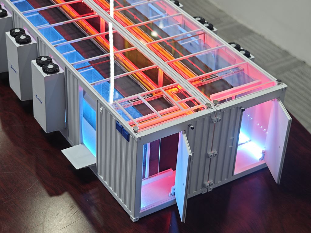
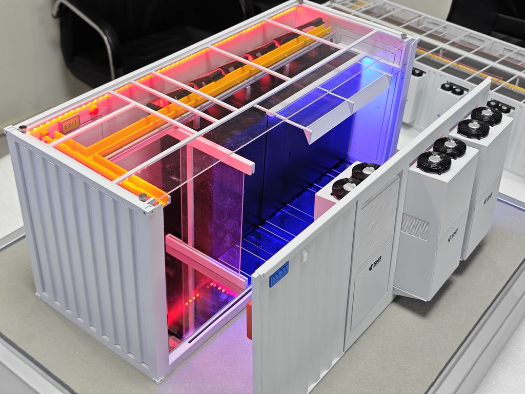
The model produced this time is an electrical equipment model for teaching display, with a scale of 1:5. The model adopts a cross-sectional display design, and the shell can be partially opened to clearly present the layout of internal components and circuit connections. The focus of production is to reproduce the structural logic and safety standards of the equipment through scientific material matching and fine manual craftsmanship, with an overall restoration rate of over 90%, meeting the needs of teaching demonstrations.
2、 Material selection and pretreatment
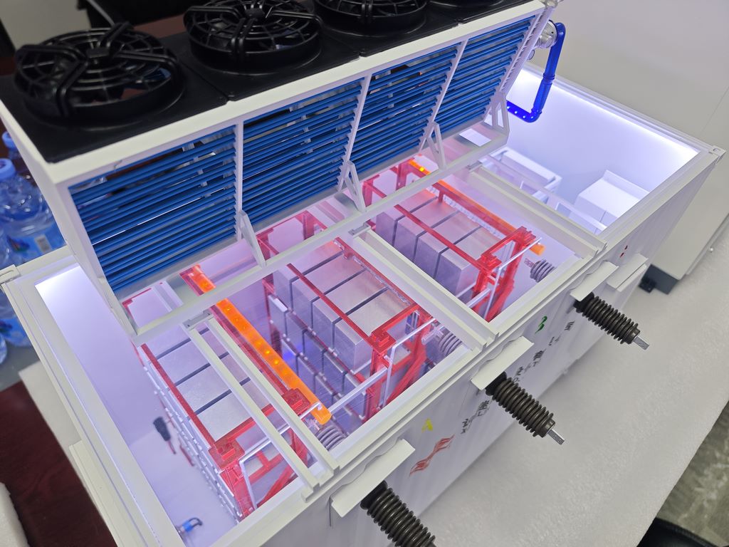
The main framework of the model is made of lightweight and easy to carve oak plywood, which ensures the stability of the overall structure. The outer shell is made of 1mm thick ABS board, which has a smooth surface and can perfectly simulate the texture of industrial plastic shells. The internal core components are made of high-density PU resin through silicone molds, ensuring uniform shape of components in the same batch. The conductive components are made of rolled copper foil, which has good ductility and can be bent into various terminal shapes. All wooden components need to undergo constant temperature drying treatment before assembly to prevent deformation in the later stage.
3、 Production process flow
The production process adopts an assembly logic of “inside out”. Firstly, use oak plywood to construct the internal support framework of the equipment, with all joints using a double fixing method of mortise and tenon structure combined with adhesive. The circuit board substrate is carved from white ABS board, and regular component holes are drilled with a micro drill bit. After the resistors, capacitors, and other components are molded by resin casting, the burrs are manually trimmed by the craftsman, and then precisely installed in the corresponding positions with special glue.
Line connection is a technical difficulty. According to the circuit schematic, route colored insulated wires of different diameters according to functional zones. The high-voltage part uses yellow and red wires, and the control circuit uses blue wires. All cables are arranged along the preset cable tray and fixed with micro wire clips to maintain the industrial aesthetic of horizontal and vertical alignment. The openable shell is connected to the main body through a micro hinge, and the opening and closing mechanism is repeatedly adjusted to ensure smooth operation.
4、 Coloring and surface treatment process
Clean all components before painting to remove processing residues. Firstly, apply a gray primer as a whole, which can unify the base color and inspect surface defects. The main body shell adopts industrial gray matte paint, which forms a uniform coating through three thin sprays. Internal components are color coded and coated according to their functions: circuit breakers are painted in striking orange, transformers are painted in dark gray, and wiring terminals retain their original metallic color.
Line identification is the key to teaching function. Use a 000th wire marker to mark the main circuit with a color ring. Red represents the live wire, blue represents the neutral wire, and yellow green represents the ground wire, which fully complies with electrical safety regulations. After completing all painting, apply two layers of matte protective paint as a whole, which not only eliminates reflection for easy observation, but also protects the paint surface for durability.