Customization of Aircraft Engine Models
Case Study of Aircraft Engine Display Model Production
1、 Project positioning and production objectives
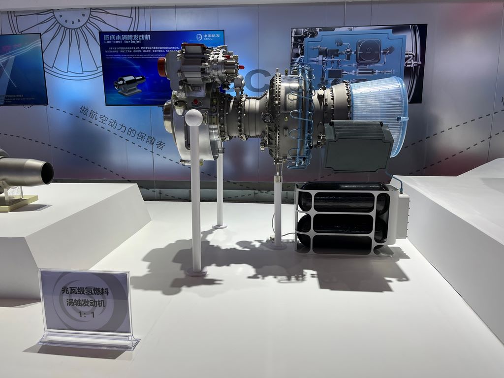
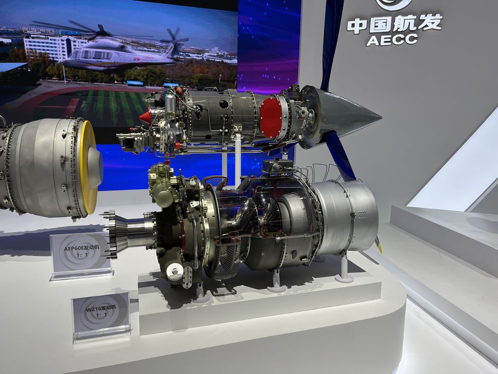
This production is a 1:1 scale aircraft engine display model, specifically designed for the science popularization exhibition at the Aviation Science and Technology Museum. The model adopts a full section design, fully displaying the internal structure of the engine from the intake to the exhaust nozzle, including core components such as the compressor, combustion chamber, and turbine. The production goal is to achieve a restoration rate of over 90% through precise craftsmanship, allowing the audience to intuitively understand the complex structure and working principles of aircraft engines.

2、 Material selection and characteristic matching
The main framework of the model is made of welded steel structure, ensuring stable support for the engine body that is several meters long. The internal core components are selected differently according to functional requirements: the compressor and turbine blades are made of high-strength engineering plastics through 3D printing, which can ensure detail accuracy and control overall weight; The combustion chamber components are made of aluminum alloy precision casting, and the real heat dissipation holes and fuel nozzle structures are reproduced through CNC machining; Various pipeline systems use stainless steel pipes and copper pipes of different diameters to faithfully reproduce the complex internal network of aircraft engines.
3、 Sectional design and manufacturing process
The production adopts a process scheme of “segmented dissection”. Firstly, based on the actual structure of the engine, design multiple parallel sections, each displaying a different functional area. Use a five axis precision carving machine to cut metal parts, ensuring that each section is smooth and flat, and displaying the three-dimensional relationship of the internal structure. The installation angle of the blade has been precisely calculated, and it maintains its complete aerodynamic shape even after cutting.
The air inlet part is made of transparent resin cast as a whole, and the internal compressor blades are arranged in layers, creating a visual effect with a strong sense of depth. The combustion chamber area is innovatively made of high-temperature resistant acrylic material, and the combustion effect is simulated through an internal LED lighting system. All cut surfaces are finely polished and coated with a transparent protective layer to prevent oxidation and enhance the metallic texture.
4、 Painting and Color Planning
The painting scheme follows the principle of “functional visualization”. The engine casing adopts the matte titanium gray standard of the aviation industry, and all cut surfaces retain the original metal color and are sprayed with transparent protective paint. The internal components are color coded according to functional zones: the compressor area uses blue-green color scheme to represent the intake flow, the combustion chamber area uses warm yellow color scheme, and the turbine part uses red to indicate the high-temperature area.
The piping system is classified by function: the fuel piping is brown, the oil piping is yellow, and the control system wiring is blue. All color boundaries are laser engraved with 0.3mm deep isolation grooves, and then manually and accurately colored. Install stainless steel nameplates next to key components, using etching technology to label names and functional descriptions.