Manufacturers who customize various engine models
High fidelity engine model production plan
1、 Design planning and process selection
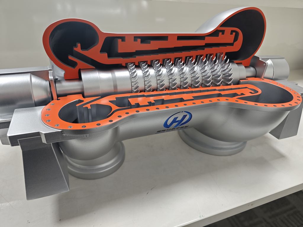
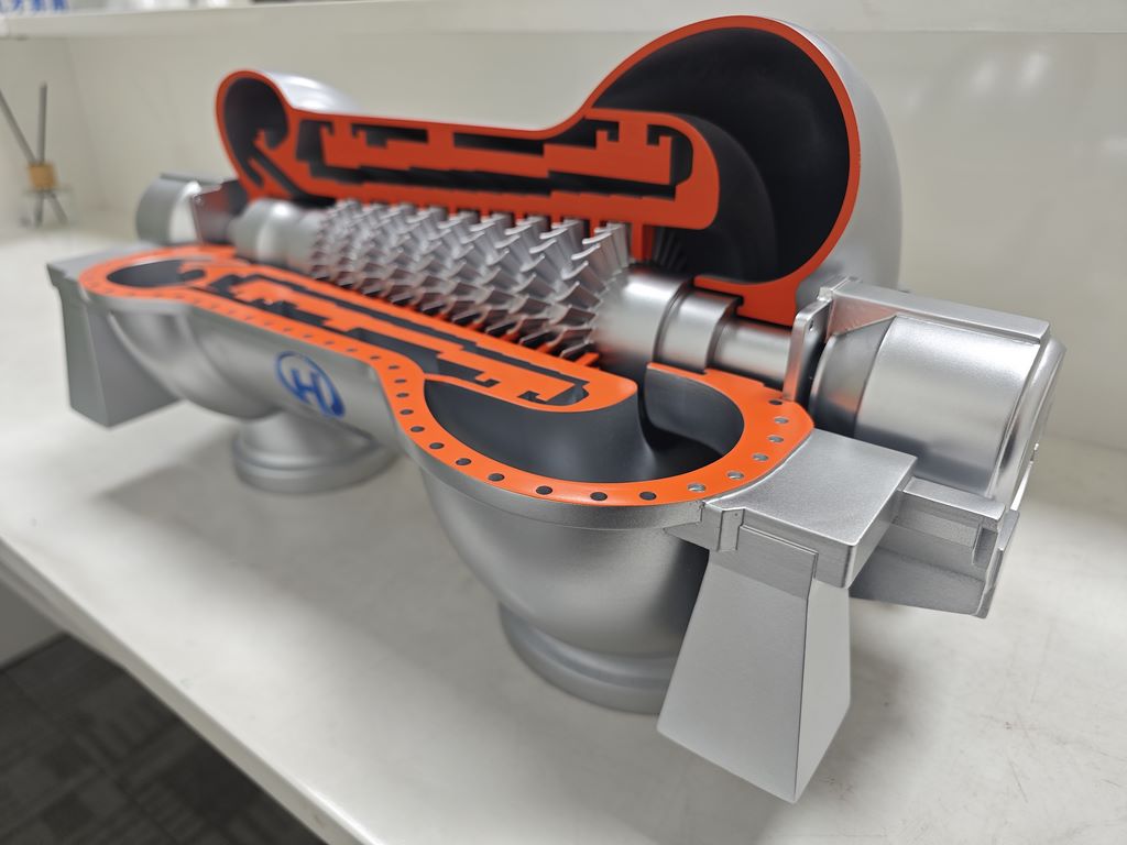
The primary step in making engine models is design planning. Based on real engine drawings or 3D scanning data, perform digital modeling at a scale of 1:5 to 1:20 in software such as CAD or Rhino. Modeling should focus on preserving the geometric features of the aerodynamic shape, internal flow channels, and core components (such as blades and combustion chambers), and design a cut on one side of the model to expose the internal structure through transparent materials, enhancing the display effect
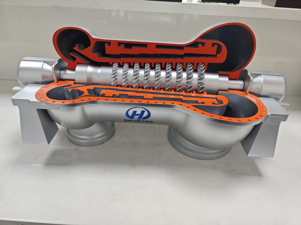
In terms of molding technology, a strategy combining additive manufacturing and subtractive manufacturing is adopted. Complex curved components such as turbine blades and compressors are printed using SLA or SLS photopolymerization 3D printing technology to ensure the accuracy and consistency of the blade array; The load-bearing frame and other linear structures are made of CNC machined aluminum alloy or engineering plastic to ensure overall stability
For rotating parts that require high strength, such as rotors, carbon fiber hot pressing or aerospace aluminum CNC precision carving can be preferred
Dynamic functional integration is the key to enhancing the realism of models. Built in micro motor drives the fan to slowly rotate, coupled with LED lights to simulate combustion chamber flames. The high-end version can add a low-speed airflow device, which uses transparent ducts to guide the airflow and simulate the workflow of intake compression combustion exhaust
2、 Material configuration and component manufacturing
Material selection should take into account texture, weight, and processability:
Shell and skin: ABS engineering plastic or aluminum alloy, balancing metallic texture and lightweight requirements
Blades and rotating components: Carbon fiber or aerospace aluminum, ensuring high strength and precise curvature reduction
Internal skeleton: Nylon (3D printed) or lightweight wood, achieving hollow weight reduction design
Transparent cut panel: made of acrylic or light cured resin, providing high transparency and easy cutting and shaping
Connectors and detailed structures: low-cost materials such as copper wire and staples can simulate miniature structures such as pipelines and connecting rods
Key points for making core components:
Compressor and turbine: proportionally restore the angle and spacing of multi-stage blades, and the impeller is CNC or high-precision 3D printed
Combustion chamber: made of colored transparent organic glass, with LED lights added inside to simulate flame effects
Shaft system and pipeline: Copper plastic wire represents oil pipeline, and silver white organic glass is used to distinguish the texture of bearing parts
3、 Post processing and texture improvement
Surface refinement is the core step in restoring realism. After removing the support from the printed part, use 400 to 2000 grit sandpaper to polish the joints step by step, and then use polishing paste to treat the matte or high gloss effect. Calibrate the spacing and angle of moving parts (such as blades) to ensure no shaking during rotation
Layered implementation of painting process:
Primer treatment: Apply black primer as a whole to enhance the adhesion of metallic paint
Layered coloring:
The nozzle adopts black iron color, the middle section transitions to copper color, and the front section uses burnt iron color to reflect the temperature difference of the metal
Thin spray transparent blue and transparent yellow at the root of the blade, welding seams, etc., to simulate high-temperature oxidation marks
Use silver gray dry sweep to enhance the three-dimensional effect of protruding pipelines, bolt heads, and other parts
Aging treatment:
Apply semi transparent enamel paint (ochre color+fuel color) to the fuel tank mouth and bearings, and pull out the dripping marks along the direction of gravity
Key friction areas (such as piston rods) should be lightly wiped with a pencil to show metallic luster
Identification and protection: Add the manufacturer’s logo and warning labels through water stickers or silk screen printing, and finally spray matte or semi gloss protective paint to achieve a uniform texture