Coating machine model manufacturer
Coating machine model production plan
1、 Design planning and overall architecture
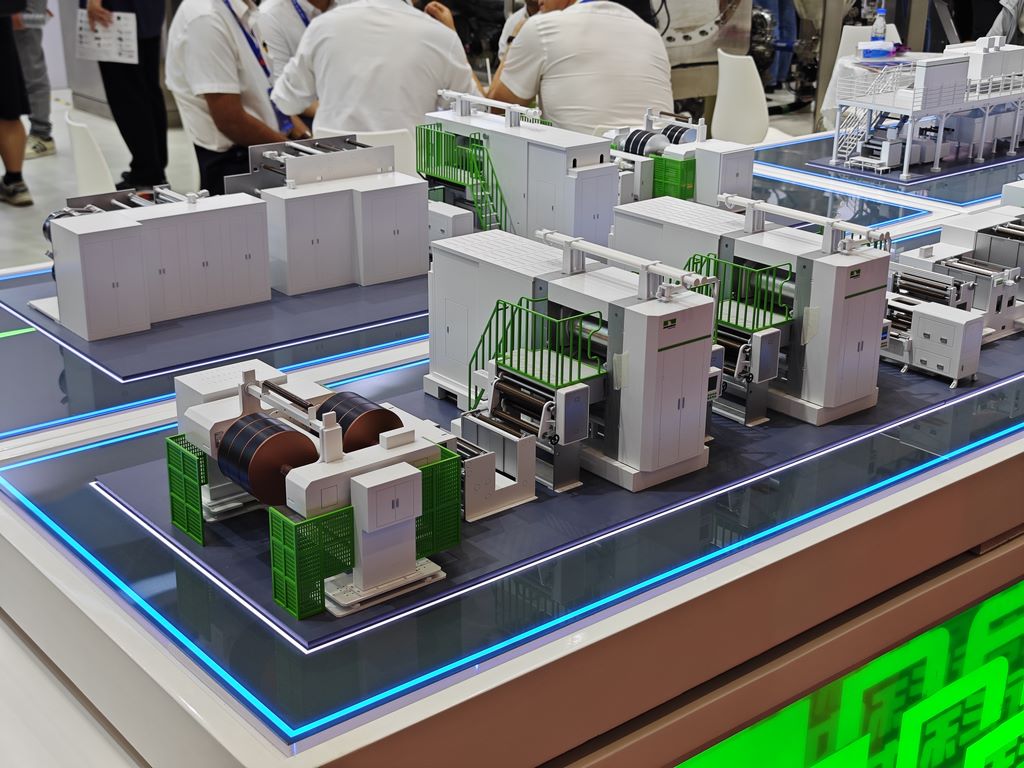
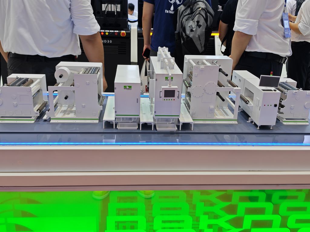
The primary task of making a coating machine model is to carry out overall design planning. Based on the structural characteristics of a real coating machine, a digital model is constructed using 3D modeling software with a reduced scale of 1:10 to 1:20. The design should focus on highlighting the core components of the coating machine: unwinding device, coating head, drying oven, and winding device. To achieve a 90% reduction rate, the core components of the coating head should be designed with cutting, and the internal die structure and slurry flow path should be displayed through a transparent window, so that the model has both visual integrity and internal mechanism visibility
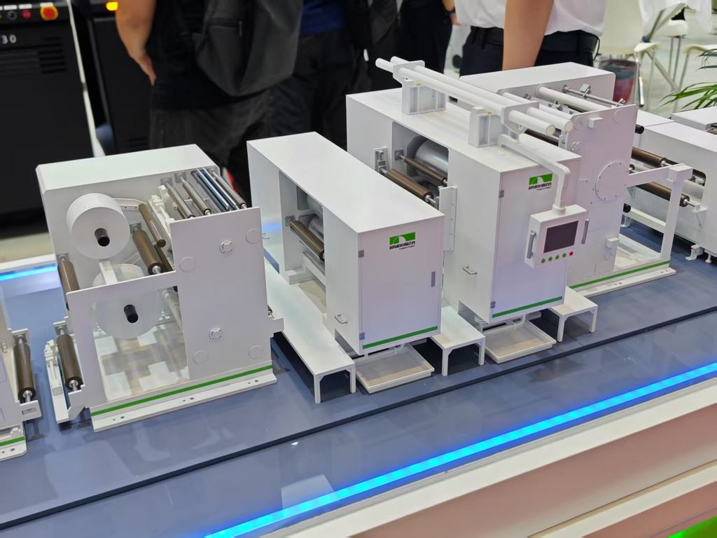
The structural layout adopts a linear assembly line design, simulating the substrate winding path of a real coating machine. Leave appropriate intervals between each module to facilitate the continuity of the coating process flow. In terms of dynamic function, the built-in micro motor drives the roller to rotate synchronously, and the LED light indicates the heating area to reproduce the device’s operating status
.
2、 Material selection and component manufacturing
The main framework is composed of ABS engineering plastic and aluminum alloy. ABS plastic is easy to shape and lightweight, suitable for making machine casings and protective covers; Aluminum alloy provides the necessary structural strength for making support frames and roller bearing seats
.
The material selection of core components should take into account both functionality and aesthetics:
Coating die head: Made of high gloss stainless steel or electroplated resin, it expresses the metallic texture of precision instruments
Transport roller: Use aluminum alloy pipe surface oxidation treatment or plastic roller vacuum coating to simulate metal effect
Substrate simulation: Using transparent PET film to simulate polarizer and demonstrate the dynamic effect of coating process
Pipelines and cables: Fine diameter copper pipes and silicone wires represent hydraulic pipelines and electrical connections
In terms of special structural processing, the flow channel cavity inside the coating head is 3D printed with transparent photosensitive resin to facilitate the observation and simulation of slurry flow; The scraper mechanism is made of thin steel sheets, retaining adjustable functions but limiting the range of travel
3、 Manufacturing process and assembly flow
The molding process adopts a strategy of combining multiple technologies. Complex curved components such as oven shells are 3D printed using SLA photopolymerization to ensure smooth appearance; High precision parts such as mold lip are CNC precision carved to ensure accurate key dimensions; Large planar structures are made by laser cutting acrylic sheets to improve efficiency and ensure edge flatness
.
The assembly process follows the principle of modularity and is carried out in sequence:
Assembly of base and frame: First install the main load-bearing structure, level and reinforce the connection points
Installation of transmission system: Install the unwinding roller, guide roller, and winding roller in sequence to ensure the parallelism of the roller system
Coating head positioning: Adjust the gap between the coating die head and the back roller to the optimal display state
Auxiliary system integration: Install auxiliary devices such as gas pipelines and heating lamps
Dynamic component debugging: Connect the motor and lighting system to test the smoothness of operation
The key assembly points include: the installation of the roller must ensure that the horizontal error is less than 0.5 degrees; Positioning device for adjusting the gap between the mold head and the back roller; The tension of the transmission belt is moderate to avoid slipping or being too tight
4、 Surface treatment and coating process
Surface finishing is the key to improving the texture of the model. All 3D printed parts need to go through processes such as support removal, sandpaper polishing (gradually processed from 400 mesh to 2000 mesh), and polishing paste polishing. Passivation treatment is applied to metal parts to prevent oxidation, and acrylic special polishing agent is used to restore transparency to transparent parts
.
The coating process adopts a layered coloring method:
Primer treatment: overall spraying of gray primer to enhance adhesion, and targeted selection of primer types for different material areas
Color separation spraying: The main frame is made of mechanical ash, the transmission components are made of metallic silver, and the coating head area retains the original color of stainless steel but adds highlight emphasis
Identification restoration: Add equipment nameplates, operation signs, and safety warning signs through water stickers or screen printing
In terms of aging and texture expression, there are slight silver scratches on the contact points of the rollers, indicating wear marks; Simulate slurry residue with transparent brown diluted coating around the coating head; Apply rust color to the bolt connection points to enhance realism. Finally, spray semi gloss protective paint to achieve uniform glossiness