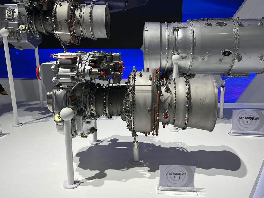
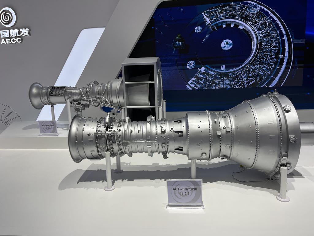
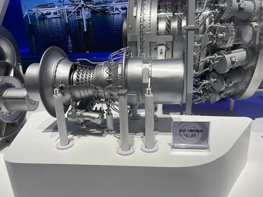
Engine model customization
Detailed Explanation of Gas Turbine Model Manufacturing Process
1、 Material selection and basic structure fabrication
Main frame material
Using lightweight wood (such as oak or aviation plywood) or ABS plastic board as the skeleton, balancing strength and processability. The turbine blades are manually cut using 0.5mm thick copper or aluminum alloy sheets to ensure a metallic texture.
The air intake and combustion chamber casing are made of 3D printed resin parts, which are printed separately to reduce residual support structures and reduce the difficulty of later polishing.
Detail component production
The pipeline system uses copper pipes of different diameters bent and welded, and the joints are filled with epoxy resin to fill the gaps; Small structures such as bolts and rivets are restored through etching or micro screws.
The rotor part needs to be assembled in layers: the central shaft is formed by turning a brass rod, and the blades are molded into resin parts through silicone molds, and then bonded to the shaft body piece by piece.
2、 Processing technology and assembly
Precision cutting and polishing
Use a laser cutting machine to process complex flat parts (such as hollow grids on the shell), and manually use a file and sandpaper (400 mesh to 2000 mesh) to gradually trim the edges and eliminate burrs.
Turbine blades need to be polished separately, using rotating tools in conjunction with wool wheels and metal polishing paste to enhance the reflective effect.
Modular assembly
Assemble in stages according to the actual model: first weld the pipeline system, then embed it into the main frame, and finally install the blades and shell. Use positioning fixtures to ensure that the coaxiality error of each component is less than 0.5mm.
Moving parts (such as rotatable rotors) need to be pre embedded with micro bearings and lubricated with silicone grease to avoid friction and jamming.
3、 Post processing and painting
Surface pretreatment
Spray ash and fill soil to inspect defects in the entire model, use atomic ash to fill the joints, dry and water grind until the surface is smooth. Metal parts need to be acid washed and passivated to prevent oxidation and discoloration.
Color separation spraying and aging
The main color is sprayed with industrial matte paint (such as TS series), and the high-temperature area (combustion chamber) adopts a gradient technique: transitioning from dark red to orange yellow, and the edge is dry swept with metallic silver to simulate the burning effect.
Penetrating liquid strengthens rivets and panel lines, oil stains are diluted with enamel paint and spot dyed, and finally sprayed with semi gloss protective paint to unify the texture.
4、 Restoration Enhancement Techniques
Reference physical surveying: Create a 1:20 scale template based on public drawings or photos, and use a projector to compare and correct key parts (such as blade angles).
Dynamic detail addition: Simulate dashboard lighting with extremely fine fiber optics, and paste reflective foil on the inside of the turbine to enhance the sense of perspective hierarchy.