Production of sectional engine model
Case study on the production of sectional engine display model
1、 Project Overview and Production Objectives
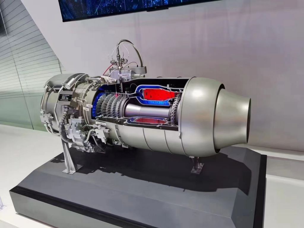
The purpose of this project is to create a 1:5 scale rocket engine profile display model, which includes two units: complete structural display and functional zoning display. The model needs to accurately present the complex internal structure, piping system, and key components of the engine, and transform precise engineering principles into intuitive visual language through scientific sectional design and color planning. The production goal is to achieve a restoration rate of over 90% and meet the needs of science popularization exhibitions and teaching.
2、 Material selection and consideration of characteristics
The main framework of the model is made of 5mm aviation aluminum plate laser cutting to ensure the stability and deformation of the supporting structure. The shell components are made of high-strength ABS plastic sheets, which are shaped into streamlined surfaces through hot bending technology. The internal core components are selected with differentiated materials based on their characteristics: the turbo pump mechanism is made of precision cast brass, the combustion chamber is formed by spinning stainless steel thin plates, and the piping system is made of copper tubes and silicone tubes of different diameters. This combination ensures both the stability of the model and the realistic texture of the metal components.
3、 Sectional design and manufacturing process
The production adopts a process scheme of “layered dissection”. Firstly, based on the three-dimensional drawing of the engine, determine the optimal profile angle to maximize the exposure of key components. Use a precision wire cutting machine to cut metal parts, ensuring a smooth and even cut. The pipeline system adopts a detachable design, connected by threaded joints, making it easy to display the internal flow path.
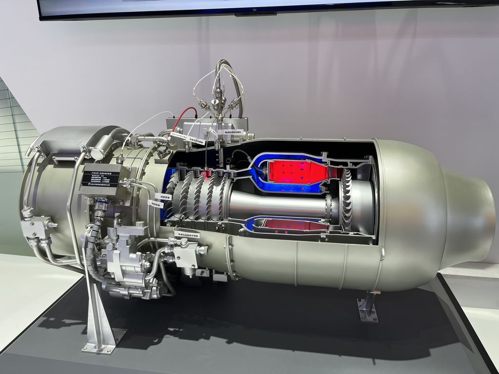
For the functional display unit, we innovatively use colored semi transparent resin to cast key areas: blue represents the liquid oxygen channel, red marks the fuel path, and gray represents the structural support. This design enables the audience to intuitively understand the flow of media and the division of labor in the system. All cut surfaces are finely polished to eliminate processing marks and display the metallic luster of the original color.

4、 Painting and Color Management
The painting process follows the principle of “prioritizing functionality and balancing aesthetics”. The main body shell is sprayed with aerospace gray matte paint, highlighting the industrial texture. The internal moving parts retain their original metallic color and are only coated with a transparent protective layer. Static structural components are distinguished by dark gray to create visual hierarchy.
The functional identification system is the essence of the project: ice blue gradient printing is used around the liquid oxygen pathway, orange red warning color is applied to the fuel area, and bright yellow insulation sleeves are wrapped around the electrical circuits. All color zone boundaries are laser engraved with 0.2mm deep grooves, and then manually colored to ensure clear and neat edges. Install micro identification signs next to key components and use etching technology to create text instructions.